Integrated Systems Explained
Integrated systems share and pool information to enhance overall building efficiency.
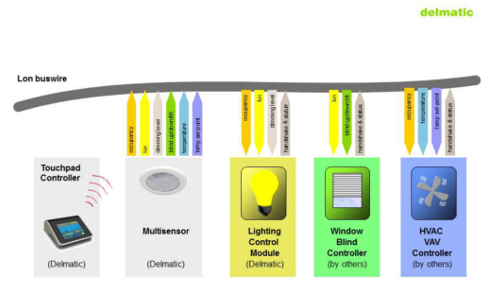
In the example below (diagram 1), a lighting control module from Delmatic, a window blind controller from a third-party supplier and a HVAC VAV controller from another third-party supplier connect to a shared Lon buswire network. The shared buswire in itself reduces material and installation costs and minimises the use of scarce resources such as copper.
click for larger image
A Delmatic multisensor monitors occupancy and daylight within each area and transmits “occupancy” (orange arrow) and daylight “lux” (yellow arrow) messages onto the shared bus.
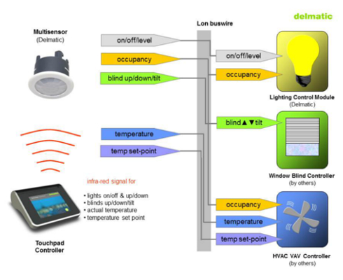
The occupancy message is routed (via software configuration) to the lighting control module and to the HVAC controller so that lighting and HVAC are controlled in relation to occupancy: the lux message is routed to the lighting control module and to the window blind controller so that both lighting and window operate in response to daylight levels.
A Delmatic touchpad controller allows the occupant to adjust lighting levels, window blinds and room temperature: infra-red commands are sent from the touchpad to the multisensor.
If the occupant raises or lowers the lighting level from the touchpad, the multisensor transmits a “dimming level” (grey arrow) message onto the buswire to the lighting control module which increase or decreases the lighting level.
If the occupant adjusts the window blind from the touchpad, the multisensor transmits a “blind up/down/tilt” (green arrow) message onto the buswire to the blind controller which adjusts the window blind.
If the occupant alters the temperature set-point from the touchpad, the multisensor transmits a “temp set-point” (purple arrow) message onto the buswire to the VAV controller which adjusts the room temperature set-point. The Touchpad Controller house an integral temperature sensor which transmits the actual room temperature to the multisensor which, in turn, transmits a “temperature” (blue arrow) message onto the buswire to the VAV controller.
The lighting, window blind and HVAC controllers all transmit status and acknowledgement handshakes onto the buswire (dark grey arrow)
The lighting control module adjusts lighting levels based on a combination of the lux reading and the user selection and whether the room is occupied or unoccupied.
The window blind controller adjusts the blind settings based upon the lux levels and the user selection.
The VAV controller adjusts HVAC based on a combination of the measured room temperature, the user set-point and whether the room is occupied or unoccupied. Typically the temperature control band is widened and the fan speed reduced in unoccupied areas and studies have shown that relaxing the room temperature by just two degrees achieves almost ten percent energy savings.
The result of the integration as shown in this example is enhanced energy savings – as both lighting and HVAC are linked to occupancy – and capital cost savings because both systems respond to a single, shared sensor.
click for larger image
Diagram 2 illustrates the routing of the signals from the multisensor to the lighting control module, window blind controller and HVAC VAV controller.
Contact us to discuss optimising your next project; and take advantage of our knowledge and experience

Integrated systems optimise building efficiency by sharing data (so that all energy-consuming services are linked to occupation and other environmental factors such as daylight), by sharing cabling and hardware (which reduces cost and environmental impact), and offering clients multiple sources of supply and support.


